Stack: Python, VLM, Edge Devices, Workflows
Video Tutorial
Overview
In this tutorial, you will learn how to integrate physical hardware with Cyberwave and deploy an autonomous safety sentinel powered by Vision Language Models. By the end of this guide, you will be able to:- Connect: Turn your local computer (Edge Device) into a smart camera node
- Stream: Send live video securely from your location to the Cyberwave cloud
- Analyze: Use AI to “look” at the video and answer questions like “Is the person wearing a helmet?”
- Automate: Trigger real-world actions (like sending an email) based on what the AI sees
Building an Active Safety Officer
In high-stakes manufacturing environments, relying on manual surveillance for safety compliance is scalable only until it fails. In this tutorial, we will transform a standard webcam into an “Active Safety Officer.” Instead of just recording footage, your camera will automatically detect if a worker is wearing the correct safety gear (PPE) and send an alert if they aren’t. We will build this system using the Cyberwave Edge SDK and a Vision Language Model (VLM) workflow.
Technical Overview
The Cyberwave stack decouples hardware from application logic and intelligence.Architecture
This tutorial rests on three architectural pillars:Ingest
Connect a physical edge device (e.g., webcam) to Cyberwave using the Python Edge SDK. This streams low-latency visual data to a Digital Twin via Cyberwave’s WebRTC and MQTT infrastructure.
Orchestrate
Develop an automated Cyberwave Workflow to fetch live visual data and inject it into a Gen AI model.
Analyze
Use a VLM (Vision-Language-Model) or VLA (Vision-Language-Action) model to process this data and automate decision-making with zero manual intervention.
Components
- Edge Device: This is your physical hardware. In this tutorial, your Laptop and its Webcam act as the Edge Device. It sits in the real world, captures video, and sends it to the cloud via the Cyberwave SDK.
- Digital Twin: A virtual replica of your physical device that lives in the Cyberwave dashboard. When your Edge Device comes online, it syncs with this Digital Twin, allowing you to see the video feed and control the device remotely from your browser.
- Workflow: An event-driven serverless function that chains: Fetch Frame → VLM Inference → Boolean Logic → Trigger Action
Prerequisites
Before starting this tutorial, ensure you have:- Hardware
- Software
- Credentials
- Linux/macOS machine with a USB Webcam
Phase 1: Connect the Edge Infrastructure
Goal: Connect your edge device (your physical hardware) to Cyberwave and ingest visual data into a Digital Twin.
Step 1.1: Install the SDK
We utilize thecyberwave-edge-python SDK to handle the hardware abstraction layer (HAL) and the network handshake between your physical camera and Cyberwave.
Open your terminal and run the following commands:
Step 1.2: Provision the Digital Twin
In the Cyberwave Dashboard, create a Digital Twin to represent your edge node:- Create a New Project and Environment.
- Add a Scene Object to the environment to create a new twin.
- Choose the specific asset from the Catalog and configure it with these details:
- Asset Type: Standard Camera
- Name: PPE Sentinel
- Navigate to Settings > API Keys and generate a new API Token.
Step 1.3: Configure the Edge Environment (.env)
Return to your local terminal and configure the environment to authenticate with the Twin.
- Create the configuration file:
- Configure the
.envfile with the following variables:
| Variable | Value/Description |
|---|---|
CYBERWAVE_TOKEN | <to be filled> Your unique API authentication token. Get this from the Cyberwave Dashboard under Settings > API Keys. |
CYBERWAVE_TWIN_UUID | <to be filled> The UUID of the specific Digital Twin this device connects to. Copy this from the Twin’s page in your Dashboard. Hover over the three dots of the asset in the sidebar, and click on “Copy Twin UUID”. (Note: If you do not see the three dots, your sidebar might be too narrow. Click and drag the edge of the sidebar to expand it.) |
CAMERA_ID | <to be set accordingly> The hardware index of the camera. - Use 0 for the default laptop webcam- Use 1 or 2 for external USB cameras |
CAMERA_FPS | 10Frames Per Second. Controls video smoothness vs. bandwidth usage. 10 is a standard balance for monitoring. |
LOG_LEVEL | INFOSets the verbosity of the logs in your terminal. Options: DEBUG, INFO, WARNING, ERROR. |
Sample .env Configuration
Step 1.4: Activate the Edge Stream
Start the daemon. The SDK will initiate an MQTT control channel and establish the WebRTC signaling path.Step 1.5: Verify Logs
Check your terminal output to verify the connection:Step 1.6: Verify the Stream
To confirm data ingestion, return to your Cyberwave Environment and “turn on” the camera in the interface. You should see live video frames streaming from your edge device directly into the Digital Twin.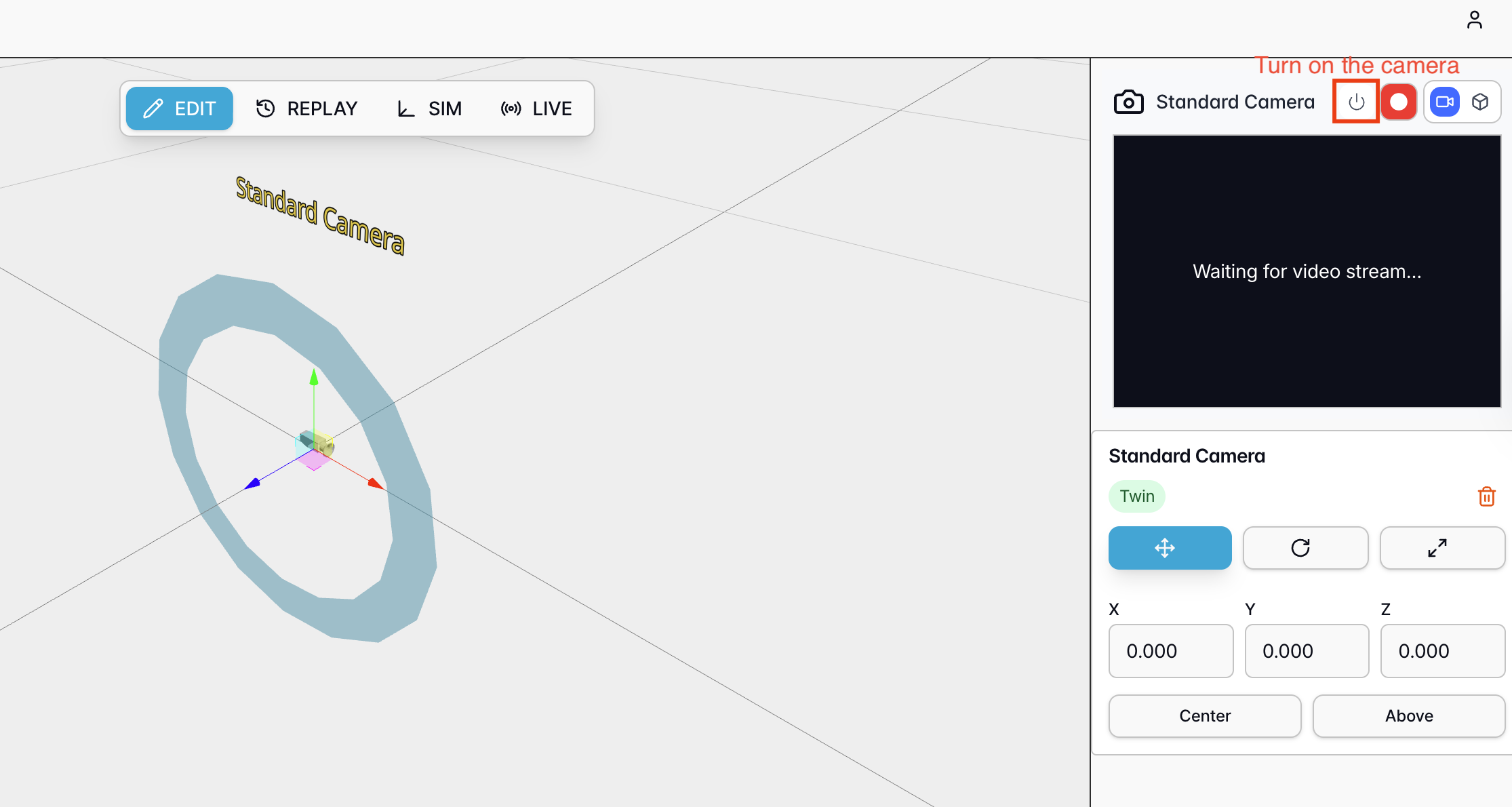
Phase 2: Configure the Workflow
Goal: Build a serverless logic flow that acts on visual data without writing backend code.
Workflow Basics
When configuring nodes, you can set inputs using:- Fixed Value: Hard-coded input parameters
- Reference Another Node: Use the output of a previous node as input
- Expression: Use templates with references to node outputs
Step 2.1: Initialize the Workflow
- Navigate to the Workflows tab in Cyberwave.
- Click Create Workflow and name it
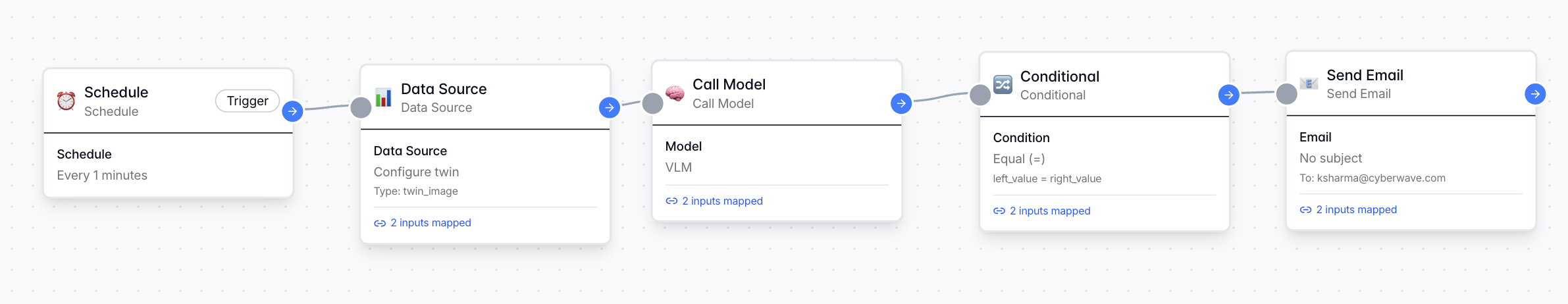
PPE-Compliance-Audit. - Trigger: Select a Schedule Trigger. Set it to run every 1 minute.
Step 2.2: Data Ingestion Node
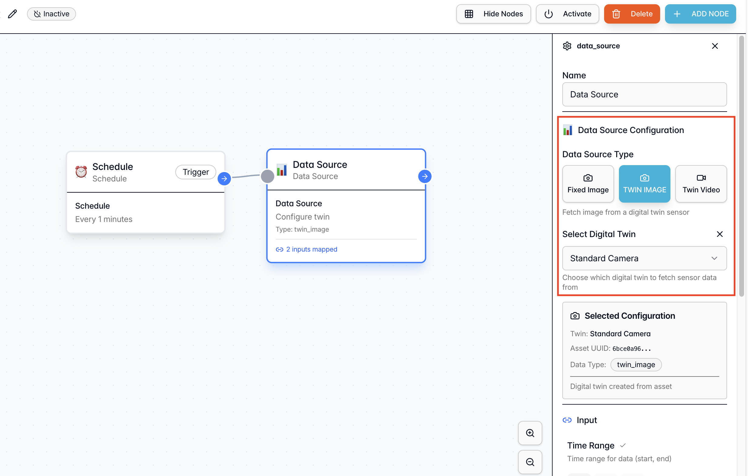
From the Node Library → Actions, add a “Data Source” node. Function: Fetches the latest sensor data (images) from the USB webcam connected to the Twin. Configuration:- Connection: Connect this node to the Schedule node by dragging the pointer from one node to another.
- Data Source Type: Twin Image
- Select Digital Twin: Choose the
PPE Sentineltwin created in Phase 1 - Output Used: We will utilize the
Image URLoutput generated by this node in the next node (intelligence node).
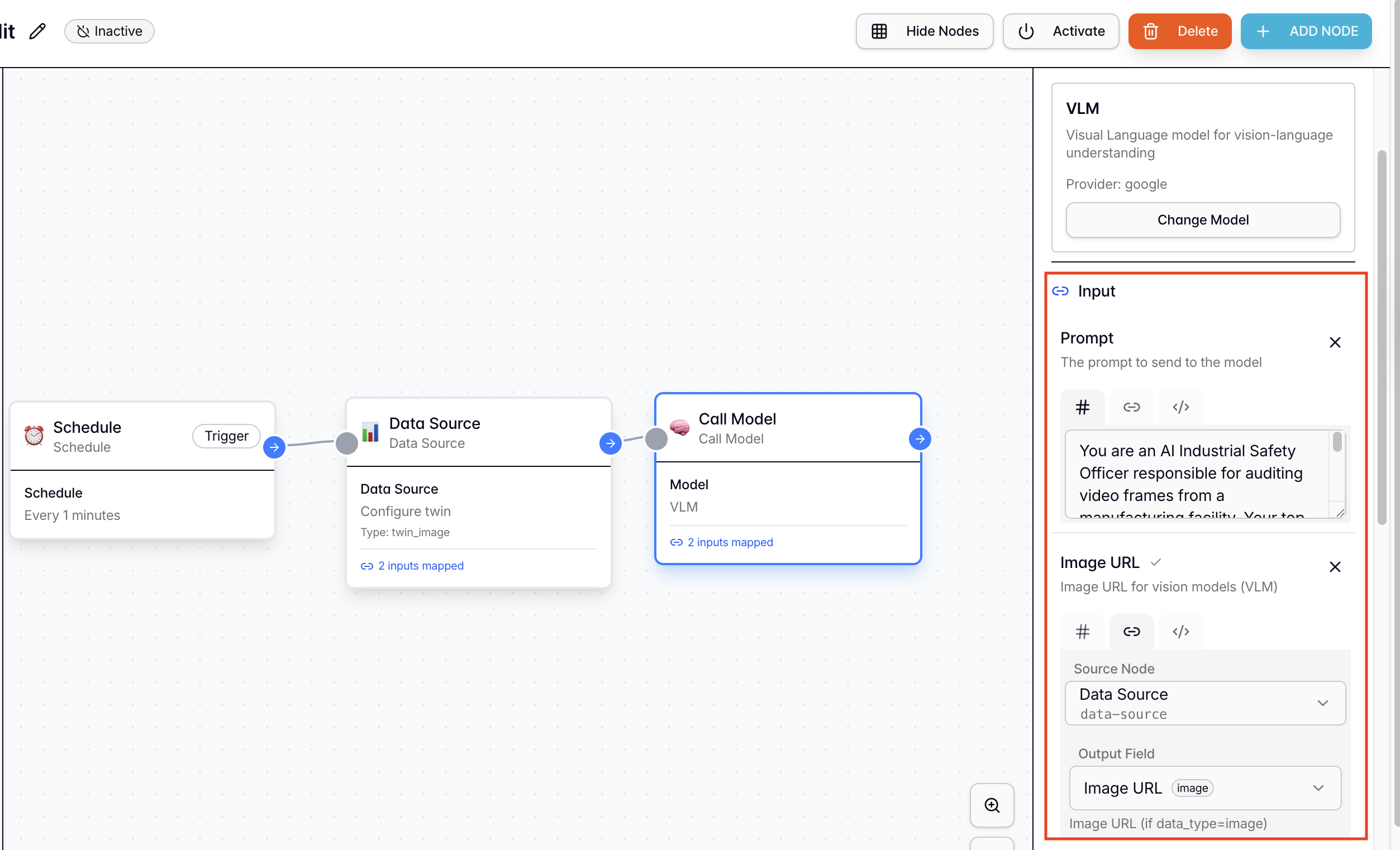
Step 2.3: Intelligence Node (VLM Integration)
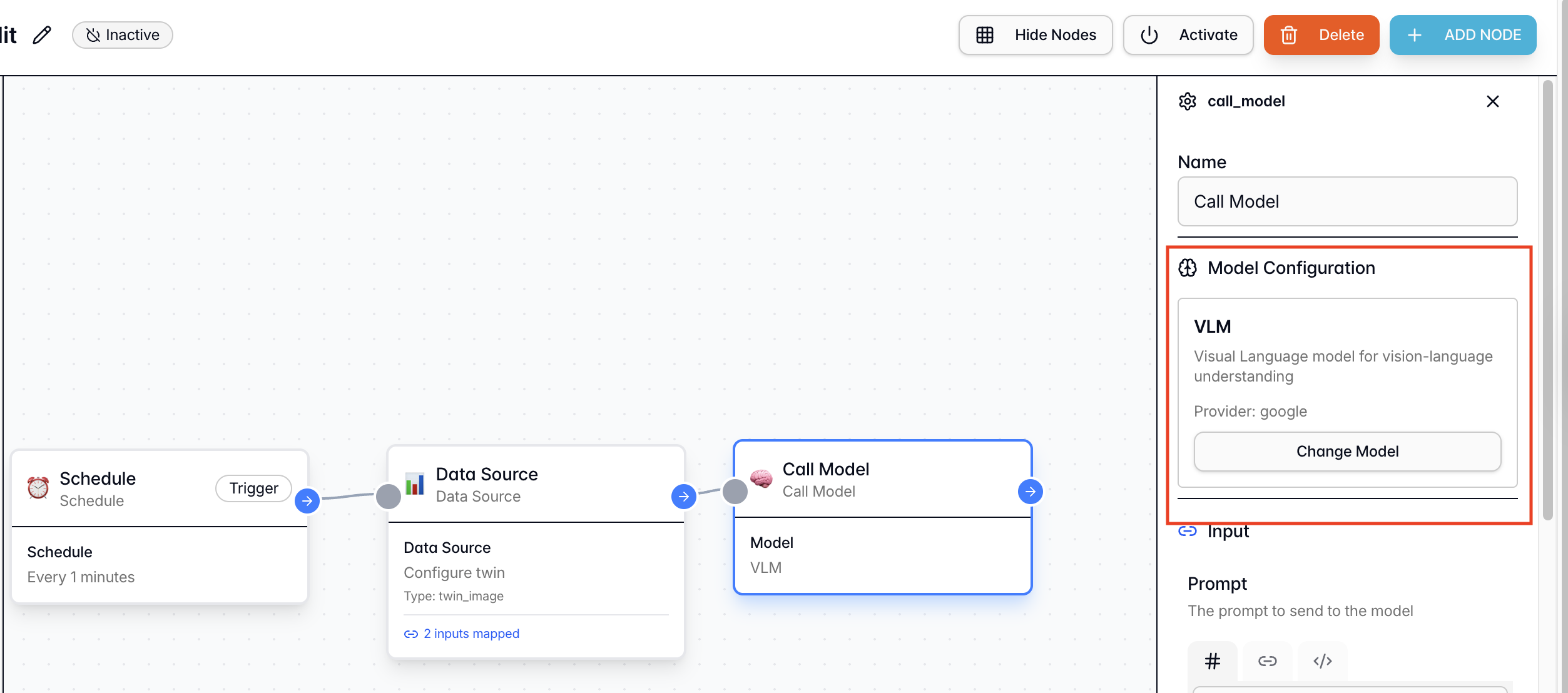
From the Node Library → Actions, add a “Call Models” node. Function: Abstracts the complexity of encoding inputs and calling AI models. It passes visual data to the VLM to analyze violations based on our prompt. Configuration:- Connection: Connect this node to the Data Source node by dragging the pointer from one node to another.
- Select Model: VLM Model
- Prompt [Fixed Value]: Copy the following strict logic prompt:
- Image URL [Reference Node]: Select the
Data Sourcenode and map itsImage URLoutput (discussed in the previous step) to this field - Output Used: We will use the
Resultvariable (string format) output generated by this node in the next node (conditional node).
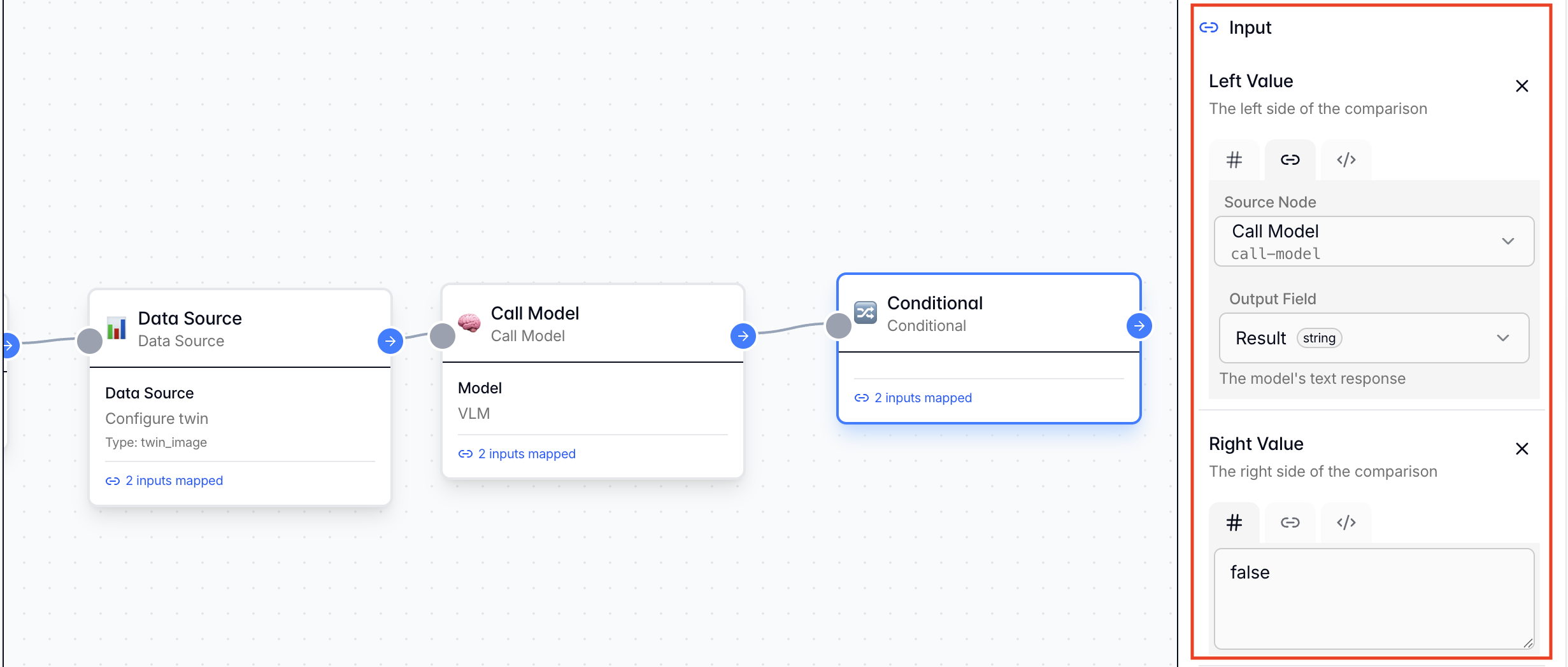
Step 2.4: Conditional Branch Node
From the Node Library → Actions, add a “Conditionals” node. Function: Parses the VLM output. If the condition is met (Violation Detected), the workflow proceeds; otherwise, it ends. Configuration:- Connection: Connect this node to the Call Models node by dragging the pointer from one node to another.
- Comparison Operator: Equal
- Left Side Value [Reference Node]: Select the
Call Modelsnode and itsResultoutput - Right Side Value [Fixed Value]:
false - Save the Configuration: Save the logic configuration to ensure the changes are saved.
false (indicating a safety violation).
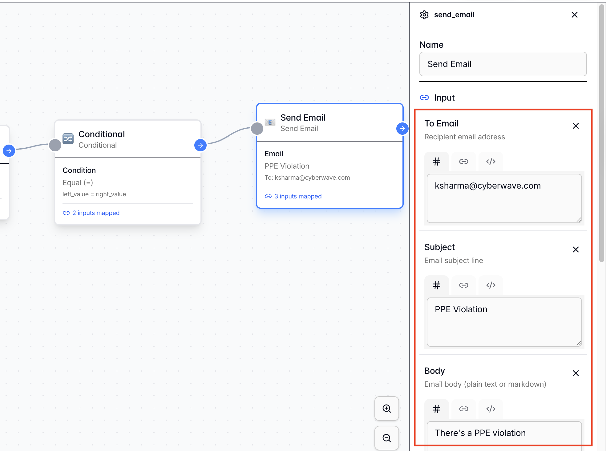
Step 2.5: Email Notification Node
From the Node Library → Actions, add a “Send Emails” node. Function: Dispatches an alert when the conditional branch is triggered. Configuration:- Connection: Connect this node to the Conditional Branch node by dragging the pointer from one node to another.
- To Email: [Your Escalation Email Address]
- Subject:
PPE Compliance Violation - Body:
There is a PPE violation detected in Zone X. Please investigate.
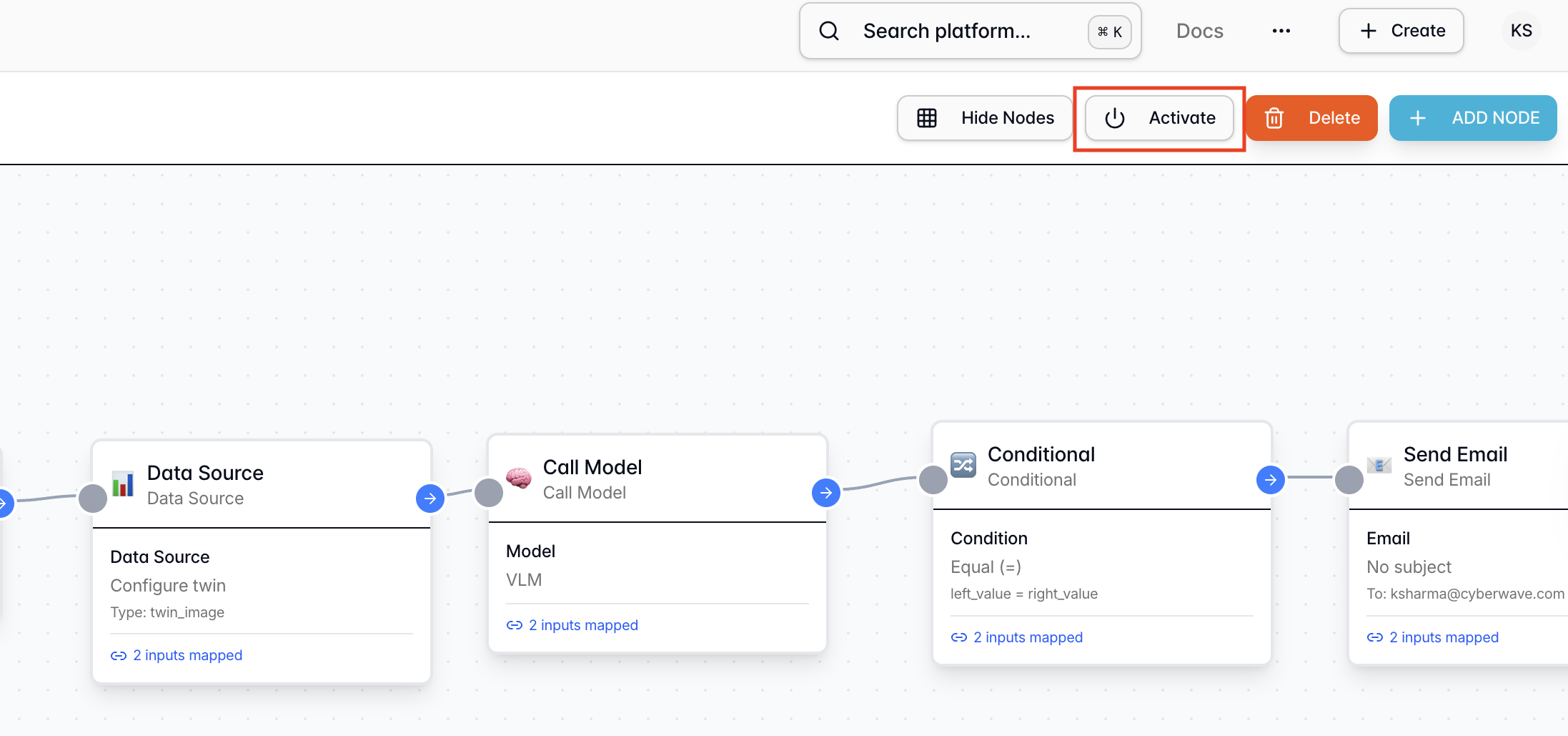
Step 2.6: Activate the Workflow
Click Activate to deploy the workflow configuration. This process automatically validates your workflow logic, ensuring it can run correctly and alerting you to any configuration errors before deployment.Your workflow is now live and will run every minute to check for PPE compliance!
Phase 3: Validate and Test
With the workflow active, it is time to physically validate the system.Pre-flight Check
Ensure the following before testing:- ✅ The
cyberwave-edgeservice is running in your terminal. - ✅ The Workflow is Active in the dashboard.
- ✅ You can see live video in the Cyberwave Digital Twin interface.
Test Case A: The “Safe” Worker
- Setup
- Action
- Execution
- Expected Result
Put on your “Hard Hat” (baseball cap) and “Vest” (bright jacket).
Test Case B: The Violation
- Setup
- Action
- Execution
- Expected Result
Remove the baseball cap (Missing Hard Hat). Keep the jacket on.
Conclusion
By decoupling the hardware (Phase 1) from the intelligence (Phase 2), you have built a solution that is robust, scalable, and upgradeable. You didn’t write complex computer vision code to detect “hats”; you simply asked a VLM to do it for you. This is the power of the Cyberwave Industrial AI stack.Troubleshooting
Edge device won't connect
Edge device won't connect
Solution:
- Verify your
CYBERWAVE_TOKENis correct - Check that the
CYBERWAVE_TWIN_UUIDmatches your Digital Twin - Check logs with
LOG_LEVEL=DEBUG
No video stream visible
No video stream visible
Solution:
- Verify camera permissions on your OS
- Try different
CAMERA_IDvalues (0, 1, 2) - Restart the
cyberwave-edgeservice
Workflow not triggering
Workflow not triggering
Solution:
- Ensure the workflow is Activated (not just saved)
- Check the schedule trigger configuration
- Manually trigger the workflow to test
VLM returns unexpected results
VLM returns unexpected results
Solution:
- Check the image quality in the Digital Twin viewer
- Adjust the prompt for your specific use case
- Increase
CAMERA_FPSfor better image quality - Ensure proper lighting in the camera view
Email notifications not received
Email notifications not received
Solution:
- Check your spam/junk folder
- Verify the email address in the workflow configuration
- Test with a different email address
Related
Workflows
Automate robot operations with visual workflows
ML Models
Register and deploy AI models
Cyberwave Edge
Connect physical hardware to Cyberwave